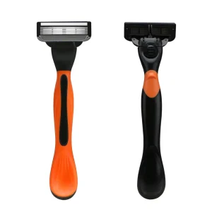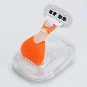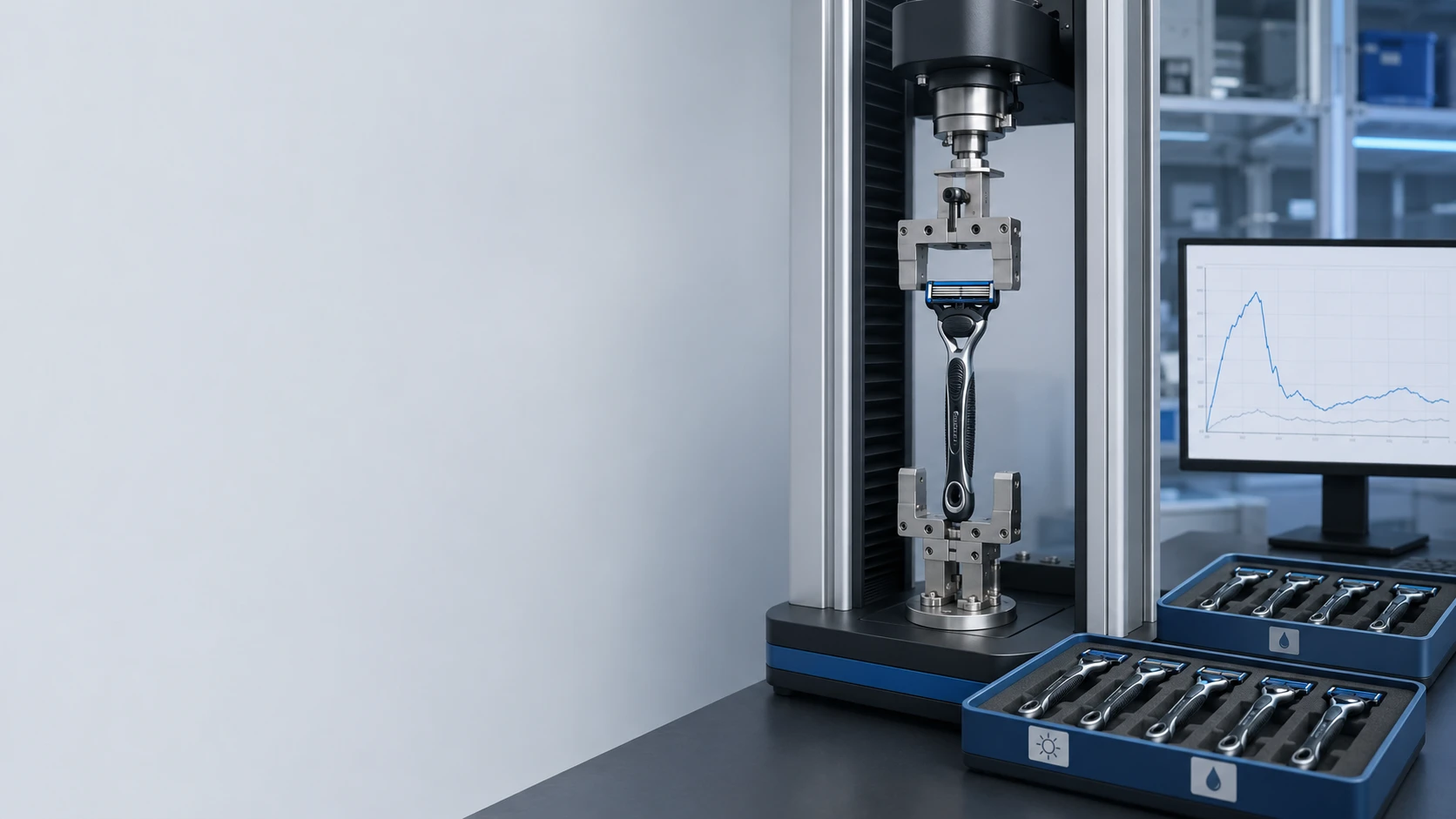
Why does a cartridge click into place during assembly yet loosen, rattle, or release after wet shaves? The problem is rarely one dimension. Retention depends on latch geometry, plastic modulus, spring force, pivot loading, dimensional stack-up, water exposure, shave-product contamination, and cycling. A connector that is too weak can detach during use; one that is too strong can frustrate refilling, damage the ejector, or cause incomplete seating. If buyer and Supplier measure different pull directions, speeds, conditioning states, or fixtures, their results cannot be compared. The solution is a controlled razor cartridge retention force program that separates attachment force, axial pull-off resistance, cartridge release force, cycling drift, and failure mode, then links each output to approved OEM drawings and production tolerances.
A valid razor cartridge retention force specification defines attachment direction, pull-off direction, speed, fixture, conditioning, cycle count, statistics and failure criteria. Haward Razor works with OEM and ODM buyers to convert these controls into a Customizable connector validation plan before pilot production.
The sections below explain how mechanical engineers and QA teams can build a comparable razor pull-off test, establish project-specific release limits, expose wet and cyclic failure modes, and control variation across the handle, cartridge, latch, spring and injection-molding process.
Separate Attachment, Retention and Release into Different Outputs
A connector cannot be characterized by one force number. The user first pushes the refill onto the handle, the latch then retains the cartridge during shaving, and an ejector or release button later disengages it. These actions have different load paths and should be tested separately.
| Mechanical Output | Recommended Definition | Primary Buyer Concern |
|---|---|---|
| Attachment peak force | Maximum compression force from first connector contact to full seating | Can the consumer install the refill without excessive effort? |
| Seating force or end position | Force and displacement at confirmed latch engagement | Can partial attachment be distinguished from complete locking? |
| Axial pull-off force | Peak tensile force needed to remove the cartridge without operating the release mechanism | Will the refill remain attached during normal and abnormal loading? |
| Release-button force | Peak force required to actuate the ejector through its specified travel | Is refill removal deliberate but still convenient? |
| Released-cartridge extraction force | Residual force required after the latch has disengaged | Does the cartridge eject cleanly or remain trapped by friction? |
Report force and displacement together. A low attachment peak followed by insufficient travel may indicate incomplete seating, not a convenient connector. A strong axial result may also be misleading if the fixture bypasses the real latch or locks the pivot in an unrealistic position.
Define the Connector Architecture and Its Load Path
Replaceable Razor platforms use different connecting structures. Common elements include flexible latch arms, detents, undercuts, receiving slots, cartridge adapters, spring-loaded plungers, ejector buttons and pivot supports. Public Razor connector patents show that attachment, retention, pivoting and ejection may share closely spaced components.
For example, US11285628B2 describes connector detents engaging handle depressions and a user-operated ejector moving along the attachment axis. Another published design, US20110088269A1, uses deflectable latch members, undercut engagement and a release mechanism. These patents illustrate architecture choices; they do not establish universal force limits.
The OEM drawing should identify:
- Connection axis and permitted attachment angle.
- Primary and secondary locating surfaces.
- Latch arm length, thickness, draft and root radius.
- Detent height and undercut engagement.
- Release-button travel and ejector contact point.
- Pivot bearings, spring plunger and return-torque interface.
- Datums used to measure cartridge position after attachment.
The Manufacturer should show how load moves through these features. Otherwise, a local dimensional correction may improve attachment force while reducing pull-off security or pivot freedom.
Control the Plastic-Part Tolerance Stack
Razor cartridge retention force is highly sensitive to molded-part variation. A few dimensions determine how far the latch deflects, how deeply a detent engages, and whether the cartridge rests against its intended support surfaces.
ISO 20457:2026 covers geometrical and dimensional tolerances and acceptance conditions for plastic molded parts. It provides a useful drawing framework, but functional connector dimensions still require project-specific tolerances.
Build a tolerance analysis around:
- Handle extension width and thickness.
- Cartridge connector opening width.
- Detent or hook height.
- Undercut depth.
- Latch-arm free position.
- Stop-surface location.
- Ejector-to-cartridge clearance.
- Pivot-bearing spacing and connector flatness.
Do not calculate only a nominal fit. Evaluate worst-case material condition, mold shrinkage, cavity-to-cavity variation and warpage. Combine the smallest latch engagement with the largest clearance to predict weak retention. Combine maximum interference with the stiffest material condition to predict excessive attachment or release force.
During validation, identify every sample by handle cavity, connector cavity, molding lot and assembly line. Pooled data can hide one cavity that consistently produces weak locks.
Build a Repeatable Razor Pull-Off Test
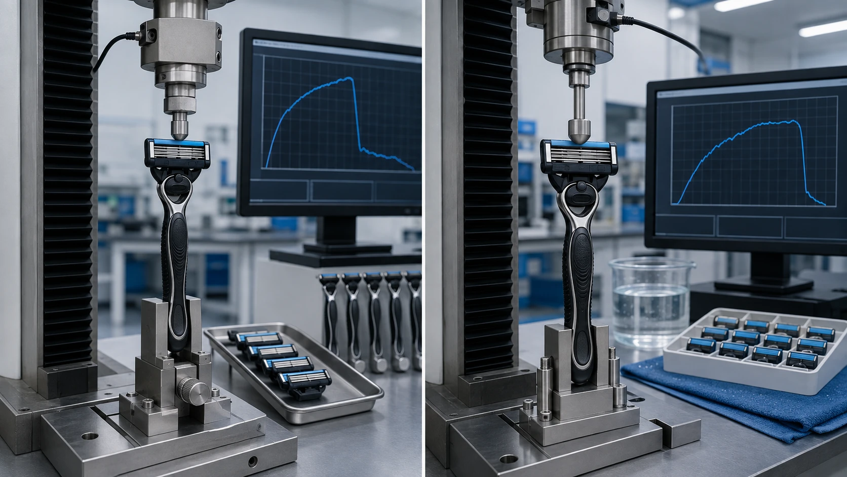
A razor pull-off test should reproduce the intended separation direction without adding fixture friction or unintended cartridge deformation. Use a low-force universal testing machine with a load cell selected so normal measurements fall comfortably within its verified range.
ISO 7500-1:2018 addresses calibration and verification of static uniaxial testing-machine force systems. Although its title refers to metallic-material testing, its force-verification principles can support equipment control for a static connector test. It does not define a Razor method or acceptance limit.
- Condition and identify the handle and cartridge.
- Attach the cartridge using a controlled procedure.
- Confirm full seating by a defined visual, tactile or dimensional criterion.
- Clamp the handle without compressing the release button or latch arms.
- Support the cartridge at points that do not distort its housing.
- Align the test axis with the approved disconnection axis.
- Apply tensile movement at the specified crosshead speed.
- Record the complete force-displacement curve and failure mode.
Validate fixture stiffness and alignment. A side-loaded fixture can turn a tensile pull into a peel test and produce a lower, more variable peak.
Use One Controlled Method for Attachment and Release Force
Attachment and release tests should use the same disciplined control as the pull-off test. The Manufacturer must specify handle orientation, actuator contact shape, test speed, preload, displacement zero, data-acquisition rate and peak-detection logic.
The following matrix provides practical development starting points. It is not a universal Razor standard, and the final values must be justified for the actual platform.
| Test Element | Illustrative Development Setting | Required Reported Output |
|---|---|---|
| Attachment test speed | 50-100 mm/min, fixed within one method revision | Peak force, seating displacement and curve shape |
| Axial pull-off speed | 50-100 mm/min, matching the approved procedure | Peak pull-off force and separation mode |
| Release-button speed | 25-50 mm/min with a rounded actuator probe | Peak force, button travel and ejection completion |
| Dry qualification sample | At least 30 handle-cartridge pairs across relevant cavities | Mean, standard deviation, range and percentile review |
| Cycling checkpoints | 0, 10, 25, 50 and 100 cycles for development screening | Force drift, damage and failure occurrence |
| Off-axis challenge | Project-defined angle, such as 5° or 10° | Retention loss and connector damage |
Do not change test speed between Supplier and buyer laboratories. Snap-fit polymers are rate-sensitive, and a faster test can produce a different peak even when the parts are identical.
Condition the Connector Before Dry and Wet Testing
Dry, as-molded testing is only the baseline. A refillable Razor is repeatedly exposed to water, warm environments, shaving gel, soap, skin oil and drying cycles. These conditions may change plastic stiffness, friction, dimensional stability and spring behavior.
ISO 291:2008 defines standard atmospheres for conditioning and testing plastics. Use it to establish a reproducible dry reference condition. ISO 62:2008 addresses water absorption of plastic specimens, but it does not replace a finished-connector wet test.
A Customizable wet matrix may include:
- Warm-water condition: assembled or separated parts exposed to 40 ± 2°C water for a defined time.
- Immediate-wet test: measure within a fixed interval after removal from water.
- Shave-product contamination: apply a controlled mass or volume of approved gel slurry to the connector.
- Wet-dry cycling: alternate defined exposure, rinsing and drying periods.
- Extended storage: evaluate dimensional recovery after drying.
Record water temperature, exposure time, chemistry, rinse method and delay before testing. “Tested wet” is not a reproducible instruction.
Cycle the Complete Handle-Cartridge System
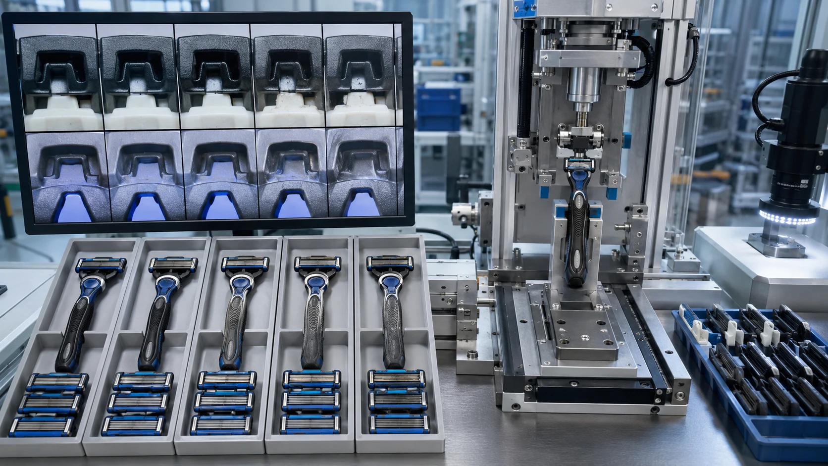
A connector may pass its first test and weaken through repeated deflection. Each attachment cycle strains latch arms, detents, springs, ejectors and pivot features. Polymer creep, stress relaxation, wear particles and root cracking can gradually reduce razor cartridge retention force.
Use an automated or controlled manual fixture that follows the real connection axis. One cycle should include attachment to confirmed seating, a dwell if required, release-button actuation and complete separation. Do not pull the cartridge off forcibly during every durability cycle unless misuse pull-off is the defined stress.
At selected checkpoints, measure:
- Attachment peak force.
- Axial pull-off force.
- Cartridge release force.
- Release-button return position.
- Cartridge free play and rattle.
- Pivot range and return behavior.
- Latch stress whitening, cracking or permanent set.
The cycle requirement should exceed the intended number of refill replacements with an agreed engineering margin. A 100-cycle development screen is useful for comparing designs, but it is not automatically the correct production specification for every Razor platform.
Challenge the Connection with Shaving and Misuse Loads
A purely axial pull does not represent every load during shaving. Skin contact can create transverse force, pivot torque and moment loading. Rinsing, tapping the cartridge against a sink, dropping the handle or attempting an angled refill attachment introduces additional stresses.
Build a risk-based challenge plan that includes:
- Transverse load: force parallel to the blade edges.
- Peel or moment load: force applied away from the connector centerline.
- Pivot-end-stop load: repeated movement to the maximum pivot angle.
- Incomplete-seating challenge: determine whether a partially attached cartridge looks deceptively secure.
- Contaminated attachment: introduce defined hair or gel contamination at the interface.
- Drop conditioning: apply a controlled drop sequence before repeating retention tests.
The most serious failure is not always the lowest measured force. A connector that appears attached but has only one latch engaged can create an intermittent field failure. Use high-speed video, sectioning or transparent development parts when necessary to understand engagement.
Classify the Failure Mode Behind Every Force Result
Peak force alone cannot identify the design weakness. Record how and where the system failed. Two samples can produce the same peak but require different corrective actions.
| Observed Failure Mode | Likely Engineering Cause | Recommended Control |
|---|---|---|
| Cartridge pulls off without visible damage | Insufficient undercut, excessive clearance or low latch preload | Review tolerance stack and engagement depth |
| One-sided release | Cavity imbalance, connector warpage or fixture misalignment | Measure left and right engagement independently |
| Latch stress whitening or fracture | Excessive strain, sharp root radius, unsuitable resin or cold molding | Revise geometry, material and molding window |
| Excessive attachment force | High interference, flash, incorrect shrinkage or stiff material | Correct critical dimensions and cavity process |
| Button moves but cartridge remains attached | Insufficient ejector travel, friction or latch timing error | Review actuator displacement and contact sequence |
| Retention declines after wet cycling | Material conditioning, wear, spring relaxation or residue buildup | Compare dry recovery and wet-state dimensional data |
Photograph the connector after failure and retain representative samples. The Supplier’s corrective-action report should connect the failure to drawing dimensions, material, mold cavity and process parameters.
Validate the Measurement System Before Setting Limits
Do not create tight acceptance limits until the refill connector validation method demonstrates adequate repeatability. Conduct a study across operators, days, fixtures and test machines. Include at least one known low-retention and one known high-retention sample where possible.
ISO 5725-2:2025 provides a framework for estimating repeatability and reproducibility of measurement methods. A full interlaboratory study may not be necessary during early development, but the principles remain useful when buyer and Manufacturer compare results.
Review:
- Load-cell resolution and verified range.
- Fixture-to-fixture alignment.
- Operator attachment technique.
- Conditioning-time variation.
- Peak-detection and filtering settings.
- Within-sample repeat testing effects.
A pull-off test is normally destructive to the tested engagement state. Do not repeatedly measure one connector and treat the results as independent samples. Use separate units or a predefined repeated-measures design.
Set acceptance limits only after separating measurement variation from product variation. Include an appropriate guard band when uncertainty is significant near the limit.
Convert Engineering Results into an OEM Control Plan
The final OEM or ODM specification should control more than a minimum pull-off value. Define the complete force window, conditioning state, cycle history, sample location, statistics and allowed failure modes.
The approved package should include:
- Handle, cartridge and connector drawings with critical dimensions.
- Material grades and approved alternates.
- Method revision for attachment, pull-off and release testing.
- Fixture drawings and equipment requirements.
- Dry, wet and post-cycle acceptance criteria.
- Cavity-level sampling requirements.
- Golden samples and reference force curves.
- Reaction plan for out-of-limit results.
- Engineering change control for resin, mold, spring, latch and assembly changes.
During pilot production, compare every mold cavity and assembly station. For mass production, the QA team may use a reduced routine test frequency supported by dimensional control and periodic full validation.
A qualified Razor Manufacturer should maintain traceability between the force result, handle lot, cartridge lot, molding cavity, assembly line and test operator. This allows the buyer to distinguish an isolated connector defect from a platform-wide design problem.
References and Method Boundaries
- ISO 291:2008: standard atmospheres for conditioning and testing plastics.
- ISO 62:2008: water-absorption characterization for plastic materials.
- ISO 7500-1:2018: verification of static uniaxial testing-machine force-measuring systems.
- ISO 5725-2:2025: repeatability and reproducibility of measurement methods.
- ISO 20457:2026: dimensional and geometrical tolerances for plastic molded parts.
- US11285628B2: detent, handle-extension and ejector architecture for a replaceable Razor cartridge.
These references support conditioning, dimensional control, equipment verification and connector architecture. They do not prescribe a universal attachment, pull-off or release-force limit for all Razor systems. Each brand must validate its limits against the actual design, intended user, refill life and foreseeable misuse.
Validate the Connection Before Approving the Refill Platform
Approve a refillable Razor only after attachment, pull-off, release, wet conditioning, cycling and failure-mode results agree. Send Haward Razor your connector drawings, material requirements, target refill life and reference samples. Our OEM and ODM team can develop a Customizable refill connector validation matrix for your project.