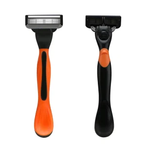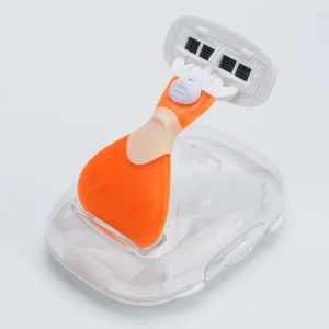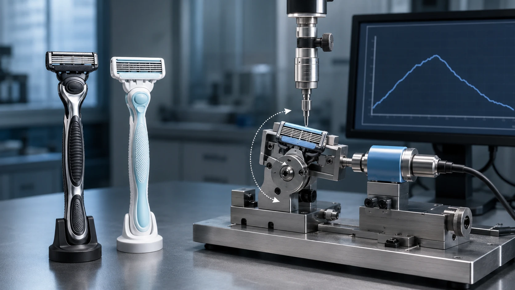
A prototype can pass an informal hand check yet fail after scale-up. The cartridge may resist its first movement, overshoot a contour, return slowly, or stop short of neutral. Uncontrolled razor pivot torque changes pressure feedback even when blade geometry is unchanged. The risk grows as resin shrinkage, spring variation, assembly offset, lubricant migration, water, and cycling accumulate. A women’s razor may lose smooth tracking around knees or ankles, while a men’s platform feels rigid along the jaw. Treating the pivot as cosmetic hides the cause behind complaints and returns. A controlled validation system solves this by measuring breakaway torque, torque through travel, cartridge return angle, asymmetry, wet response, and cycle aging before tooling approval and mass production.
For development, start with 20–40° usable travel, ≤2° return error, ≤15% side-to-side asymmetry, and stable torque after 5,000 cycles, then confirm limits through buyer trials. Haward specializes in Customizable OEM and ODM pivot systems and validates contour response with measured torque-angle data rather than hand feel alone.
The sections below show product engineers and women’s and men’s razor brands how to convert subjective feel into measurable specifications. We will examine fixture design, wet conditioning, cycle aging, failure diagnosis, and production controls that make each pivoting razor head test useful for engineering decisions.
Define the Pivot Outputs Before Selecting a Mechanism
Separate Breakaway, Running, Peak, and Return Torque
Razor pivot torque is not one number. A torque-angle curve is needed. Breakaway torque is the peak required to initiate movement from neutral; static friction and spring preload influence it. Running torque describes resistance after movement begins. Peak torque near the travel stop helps prevent uncontrolled collapse under load.
On release, the return curve shows whether the spring, elastomer, living hinge, cam, or magnetic element can restore the head. The area between loading and unloading curves is hysteresis. Excess hysteresis often appears as delayed contour recovery. A competent Manufacturer should therefore report:
- Breakaway torque in N·mm at a defined speed and starting angle;
- Torque at agreed angular checkpoints, such as 5°, 10°, 20°, and 30°;
- Maximum mechanical and usable travel angle;
- Unloading torque, final cartridge return angle, and return time;
- Left-right or off-center loading asymmetry; and
- Changes after wet exposure and cycle aging.
A progressive curve can support easy initiation and controlled recovery. A published patent example describes about 0–40° travel and 14 N·mm peak return torque, but these are examples, not universal standards. Haward D565 and D968W women’s platforms and D968 men’s architecture each require model-specific validation.
Build a Pivoting Razor Head Test That Measures the Mechanism, Not the Fixture
Control the Axis, Lever Arm, Speed, and Cartridge Datum
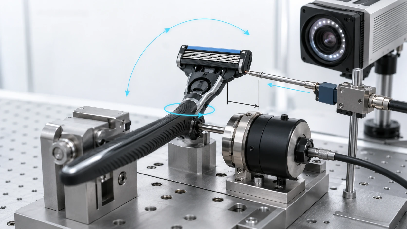
A reliable pivoting razor head test begins by locating the true pivot axis. If the load point or lever arm changes between samples, force data cannot be compared. Torque may be measured directly with a rotary transducer or calculated as T = F × r, where the tangential force is F and the perpendicular lever arm is r. The fixture must hold the handle without compressing the release button, twisting the neck, or contacting the cartridge guard.
For calculated torque, use a force system calibrated and verified through a traceable procedure. ISO 7500-1 provides relevant principles for verification of static uniaxial force-measuring systems, while ISO/IEC 17025 defines competence requirements for testing and calibration laboratories. Neither standard specifies razor performance; they strengthen the measurement chain.
- Recommended angular resolution: ≤0.1°;
- Recommended torque resolution: ≤0.1 N·mm or at least ten times finer than the tolerance;
- Controlled rotation rate: typically 5–20°/s for quasi-static comparison;
- Sampling rate: ≥100 Hz for breakaway detection;
- At least three preconditioning cycles before recording, unless first-cycle behavior is the study target.
Set Buyer-Defined Engineering Limits Instead of Copying a Universal Formula
Use a Development Window, Then Freeze the Product-Specific Specification
No universal standard assigns one correct razor pivot torque to every cartridge. Blade count, cartridge width, lubrication elements, handle angle, user group, and pivot location all influence perceived response. The table below is an illustrative starting matrix for an OEM development program. It is not a claim that every Razor should use these values.
| Engineering Output | Illustrative Development Window | Why the Buyer Measures It |
|---|---|---|
| Usable travel angle | 20–40° | Confirms adequate contour following before the hard stop |
| Breakaway torque | 2–6 N·mm | Controls initial head response and pressure rise |
| Torque at 20° | 4–10 N·mm | Defines resistance in the central working zone |
| Peak torque | 8–16 N·mm | Checks support near the end of travel |
| Return-angle error | ≤2° after 2 seconds | Detects sticking, creep, and insufficient return force |
| Off-center asymmetry | ≤15% | Detects skewed assembly or unequal bearing contact |
The brand should screen several windows in prototypes, correlate them with controlled user trials, and approve one product-specific drawing. The final specification must state conditioning, speed, fixture revision, sample age, and calculation rules. Without those conditions, a numeric limit is commercially weak and technically ambiguous.
Measure Return Consistency and Asymmetry as Distributions
A single successful return does not prove consistency. Record at least ten consecutive cycles per sample and report mean, range, and standard deviation for cartridge return angle. If a head returns to 0.5° on nine cycles but remains at 3° once, the intermittent event may be the defect the user notices.
Asymmetry requires a defined loading method. For a one-axis pivot, apply the same off-center force at equal distances from the cartridge centerline and compare the two torque curves. For multi-axis designs, test each rotational direction independently. Calculate asymmetry using the buyer-approved denominator and state the formula in the report. Common causes include:
- Unequal pivot-pin engagement or bearing width;
- Spring legs with different preload;
- Warpage in an injection-molded yoke;
- Flash, burrs, or localized texture at the sliding interface;
- Cartridge center-of-mass offset; and
- Fixture contact that unintentionally introduces yaw.
Tracking the full distribution turns razor contour response from a subjective impression into a tolerance decision.
Reproduce Wet Shaving Conditions Before Approving the Connection
Separate Laboratory Conditioning from Wet-Use Conditioning
Polymer dimensions and elastic response depend on temperature, humidity, and exposure history. ISO 291 supplies standard atmosphere principles for conditioning and testing plastics, but it does not reproduce shaving water, surfactant, or lubricant. A sound validation plan therefore uses a controlled dry baseline plus buyer-defined wet protocols.
A practical comparison may include 23 ± 2°C and 50 ± 10% RH for 24 hours, followed by immersion or spray exposure using 40 ± 2°C water for 5 minutes. If the product is expected to contact shaving foam or cleanser, the buyer and Supplier should agree on a representative solution, concentration, rinse, and test delay. Do not switch among tap water, deionized water, and detergent without documenting the change.
Measure razor pivot torque while wet when feasible and again after drying. Water can wash away lubricant, change elastomer friction, swell certain polymers, or carry residue into a narrow bearing. The meaningful result is the change from the dry baseline, not merely whether the mechanism still moves.
Use Cycle Aging to Expose Creep, Wear, and Spring Relaxation
Cycle aging should represent the mechanism’s intended service life plus a justified margin. Test at defined checkpoints rather than only before and after the full run. This reveals whether the curve changes early and stabilizes, or continues drifting toward failure. For reusable handles with replaceable cartridges, distinguish handle-cycle life from cartridge-cycle life.
| Validation Stage | Suggested Checkpoint | Key Measurements | Typical Failure Signal |
|---|---|---|---|
| Baseline | 0 cycles, dry | Breakaway, working torque, travel, return | Assembly or tolerance error |
| Early wear | 100 cycles | Torque loss and debris inspection | Flash removal or lubricant redistribution |
| Intermediate | 1,000 cycles | Hysteresis and return repeatability | Bearing wear or spring-set initiation |
| Development screen | 5,000 cycles | All outputs, wet and dry | Creep, corrosion, fatigue, or persistent sticking |
| Extended qualification | Buyer-defined, such as 10,000 cycles | Residual strength and functional return | Stop damage or return-element failure |
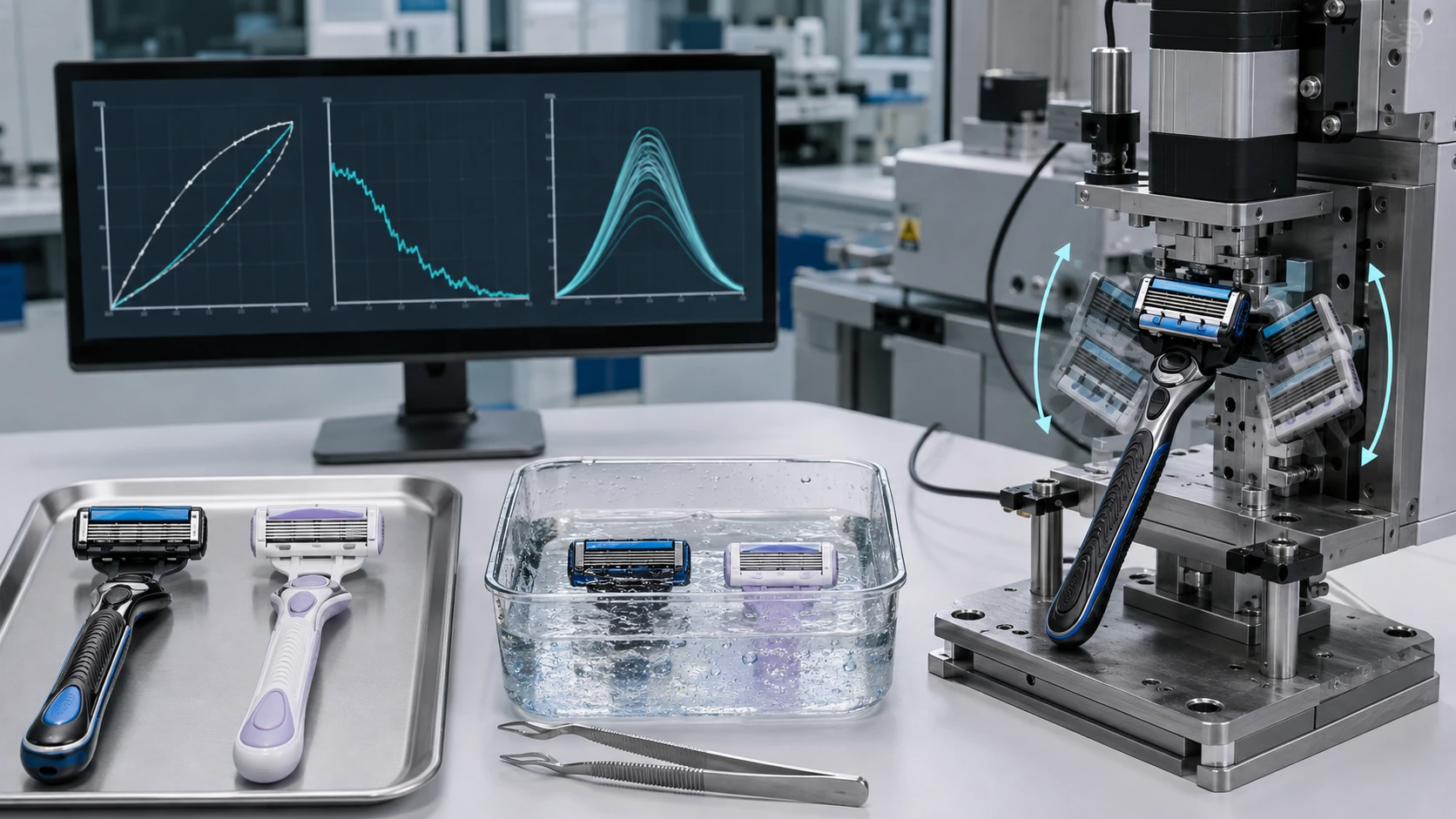
Record cycle angle, rate, dwell, temperature, and wet state. A cycle count without a load profile cannot be reproduced. The acceptance rule should limit both absolute values and percentage drift, because a mechanism may remain inside a broad limit while losing much of its original feel.
Diagnose Failure Modes from the Torque-Angle Signature
Read the Curve Before Changing the Mold or Spring
Different curve shapes point to different causes. A sharp first peak followed by a low running value suggests stiction, surface interference, or lubricant loss. Repeating spikes through travel may indicate flash, debris, or stepped contact. A smooth but progressively lower unloading curve can indicate return-element relaxation. A sudden wall before the drawing limit suggests misassembly or stop interference.
Engineers should pair the curve with dimensional and visual evidence:
- Measure pivot diameter, bearing gap, spring thickness, yoke flatness, and stop position;
- Inspect contact marks under magnification after cycling;
- Compare results by mold cavity, assembly station, material lot, and lubricant batch;
- Section failed units only after non-destructive data are saved; and
- Retain failed samples with traceable test IDs.
Do not immediately increase spring force to cure a slow return. That change may raise breakaway torque and reduce comfort. A better root-cause process separates friction, geometry, and elastic force. This is especially important when an ODM Supplier modifies a proven platform for a wider cartridge, heavier lubrication element, or different decorative housing.
Convert Failure Evidence into an OEM or ODM Control Plan
Once the cause is confirmed, freeze the interfaces that control performance. The approved data package should identify the pivot-axis datum, torque-angle envelope, stop angle, return-error limit, wet method, cycling profile, fixture revision, and golden samples. Material grade, spring temper, elastomer hardness, lubricant, and critical mold dimensions require written engineering change control because each can alter razor pivot torque.
For a Customizable OEM or ODM Razor, require first article inspection, cavity-level records, lot traceability, raw test curves, and a defined nonconformance reaction plan. During development, a practical starting sample is at least 30 assemblies across three production lots; final sampling must follow product risk and buyer confidence requirements. Use repeatability studies before comparing Suppliers, and apply the principles of ISO 5725-2 when establishing a formal method. A capable Manufacturer should monitor trend drift, not wait for units to cross a broad pass/fail limit. Haward can support platform comparison and design-for-manufacture review, while the brand approves the final user-experience window.
Make Contour Response a Measurable Purchase Requirement
Do not approve a pivoting system by hand feel alone. Send Haward your cartridge geometry, target travel, usage conditions, and lifetime expectation. We will help define a reproducible pivoting razor head test, compare OEM or ODM options, and build measurable acceptance criteria for your next Razor program.